

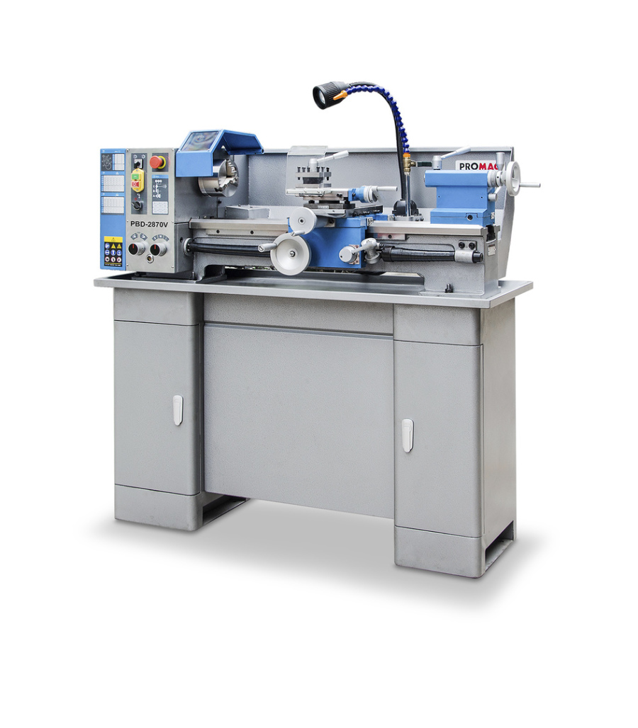
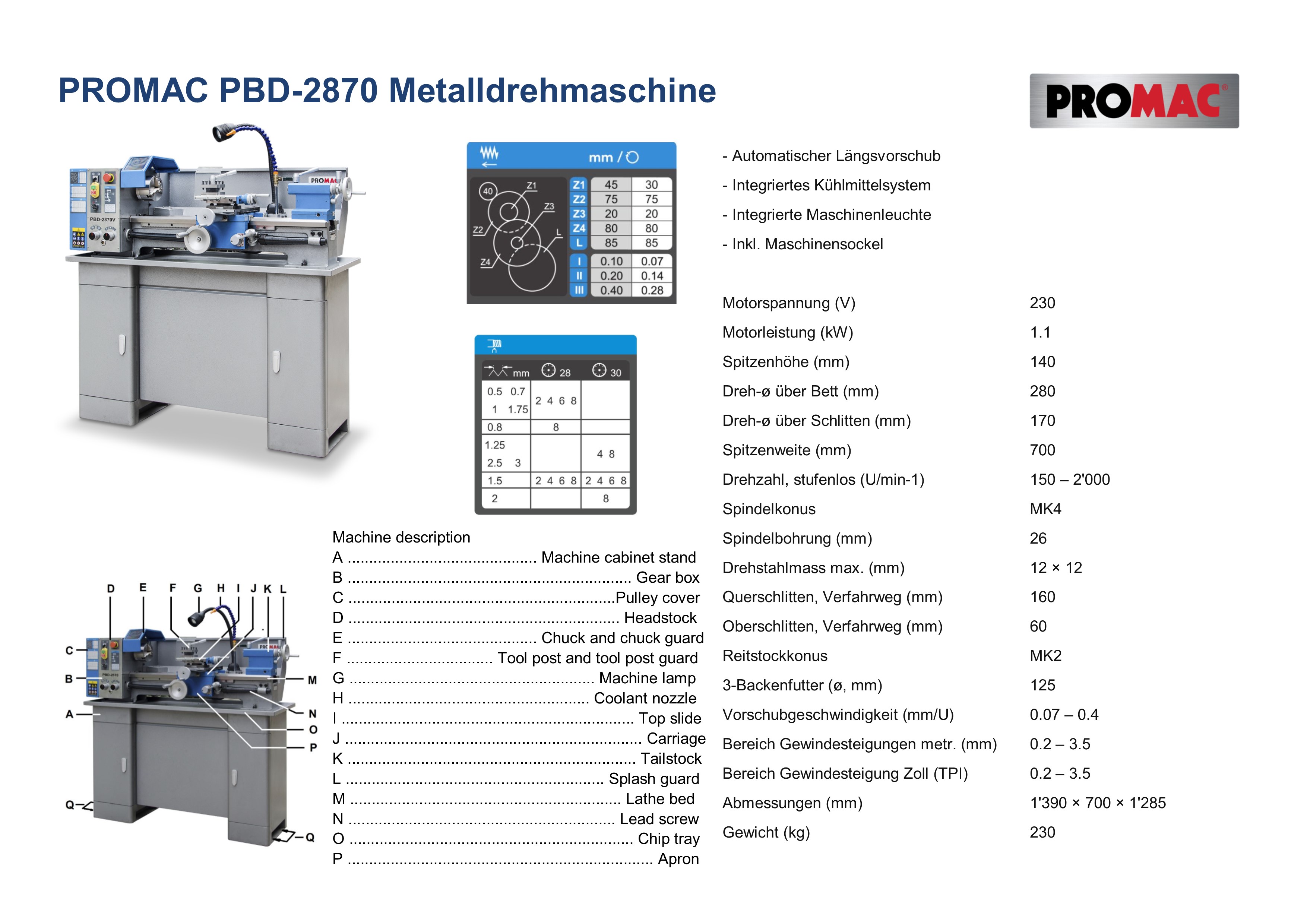
PROMAC PBD-2870 Metalldrehmaschine
Bilddaten:
Tagged Image File [74.4 MB]

JPG-Datei [529.6 KB]

JPG-Datei [802.7 KB]
Bilddaten:


JPG-Datei [55.5 KB]
JPG-Datei [51.3 KB]
JPG-Datei [34.2 KB]
JPG-Datei [27.1 KB]
JPG-Datei [22.4 KB]
JPG-Datei [62.3 KB]
JPG-Datei [44.6 KB]
JPG-Datei [43.5 KB]

JPG-Datei [38.8 KB]

JPG-Datei [25.1 KB]

JPG-Datei [30.8 KB]

JPG-Datei [32.8 KB]

JPG-Datei [36.5 KB]

JPG-Datei [30.1 KB]

JPG-Datei [36.8 KB]
- Automatischer Längsvorschub
- Stufenlose, elektronische Drehzahlregulierung
- Integriertes Kühlmittelsystem
- Integrierte Maschinenleuchte
- Inkl. Maschinensockel
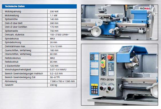

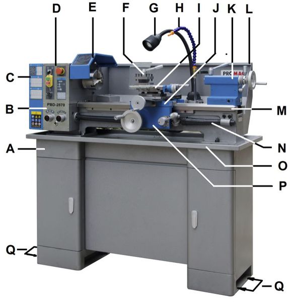
Figure 5‐1: Machine description
A ............................................ Machine cabinet stand
B .................................................................. Gear box
C ..............................................................Pulley cover
D ............................................................... Headstock
E ............................................ Chuck and chuck guard
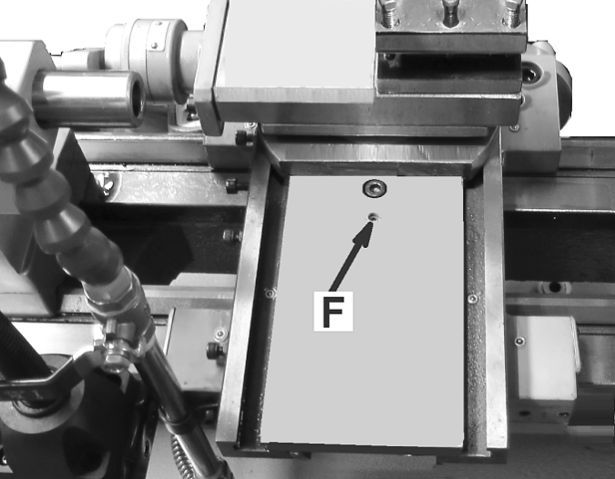
F .................................. Tool post and tool post guard
G ......................................................... Machine lamp
H ........................................................ Coolant nozzle
I .................................................................... Top slide
J ..................................................................... Carriage
K ................................................................... Tailstock
L ............................................................ Splash guard
M ............................................................... Lathe bed
N .............................................................. Lead screw
O .................................................................. Chip tray
P ....................................................................... Apron
Q .................................................... Anchor bolt holes

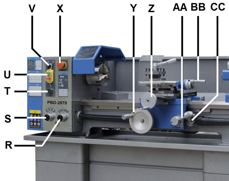
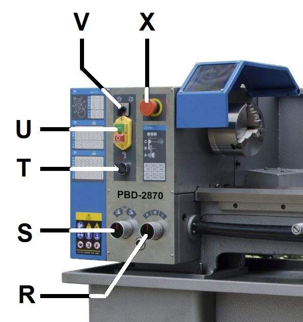
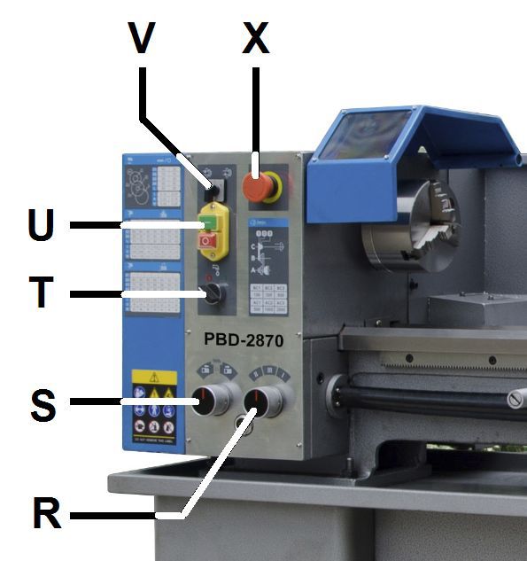
Figure 5‐2: Machine description
R ........................................... Feed speed select knob
S ........................................ Feed forward/off/reverse
T ...................................................... Coolant ON/OFF
U ............................................ Spindle power ON/OFF
V ......................................... Spindle forward/reverse
X .......................................................Emergency Stop
Y ................................................... Apron hand wheel
Z ............................................ Cross slide hand wheel
AA ......................................................... Half nut lever
BB ............................................ Top slide hand wheel
CC ........................................................ Threading dial

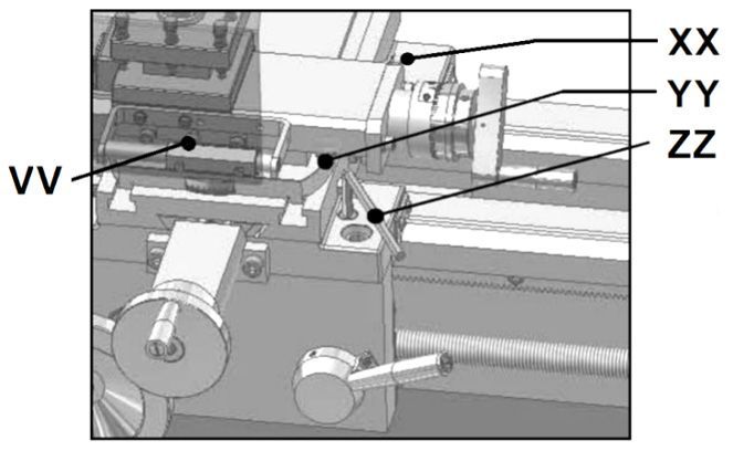
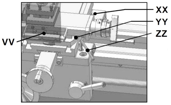
Figure 5‐3 Machine description
VV ......................................................... Top slide lock
XX ...................................................... Cross slide lock
YY ................................... Top slide taper adjustment
ZZ ........................................................... Carriage lock

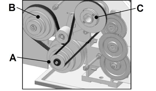
8.1 Changing spindle speed
The speeds of the lathe are controlled by the position of the
belt on the pulleys (Fig 8‐1).
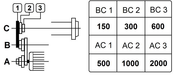
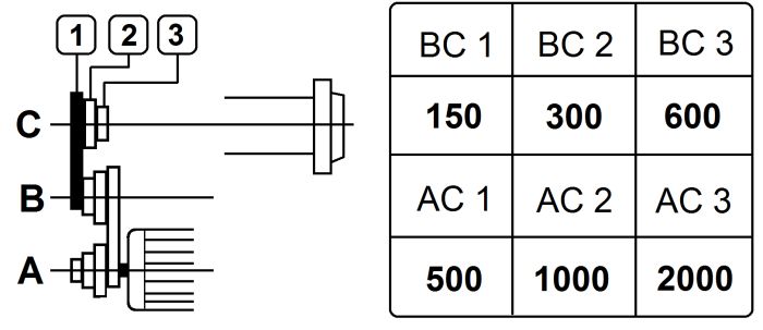
Figure 8‐1: Spindle speed chart

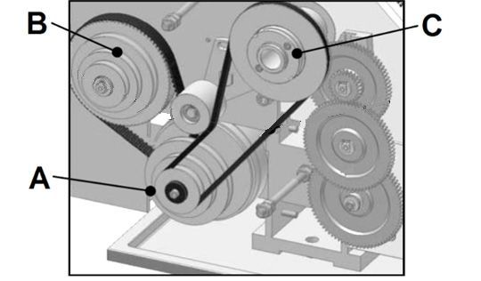
Figure 8‐2: Change gear setup
Remove the pulley cover.
The rotational speed of the lead screw, and hence the rate of
feed of the cutting tool, is determined by the gear
configuration and by the feed speed select lever (R, Fig 5‐2).
Assemble the gears with desired setup (Fig 8‐2)
Adjust gears to mesh with upper and lower gear.
Placing ordinary paper in between gears helps to adjust for
correct gear spacing (… remove the paper afterwards!).
Reinstall the pulley cover

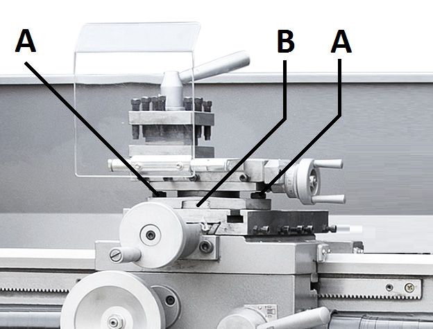
Figure 8‐4: Taper turning with top slide
By angling the top slide, tapers may be turned.
Loosen two hex nuts (A, Fig 8‐4) and rotate the top slide
according to the graduated scale (B).
Refer to Figure 9‐1:
R ............................................. Feed select knob
S ............................... Feed forward/off/reverse
T .............................................. Coolant ON/OFF
U .................................. Spindle power ON/OFF
V ................................. Spindle forward/reverse
X .............................................. Emergency Stop
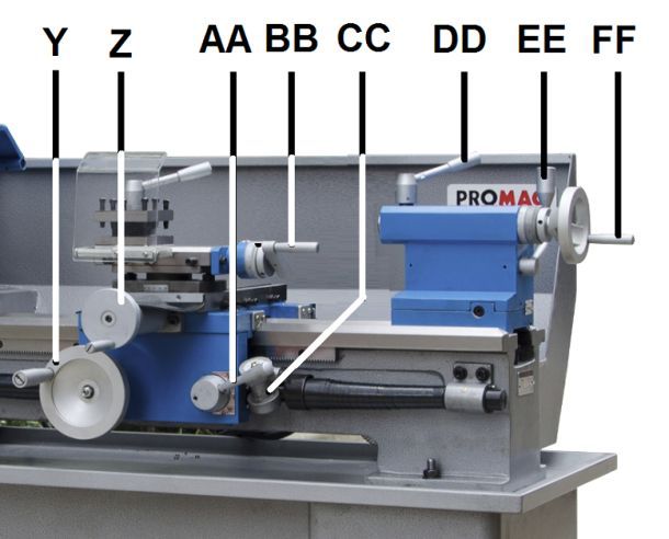
Figure 10‐6: Machine controls
Apron travel (Y, Fig 10‐6), cross travel (Z) and top slide travel
(BB) can be operated for longitudinal and cross feeding
The correct feed depends on the material to be cut, the cutting
operation, the type of tool, the rigidity of the work piece
chucking, the depth of cut and the desired surface quality.
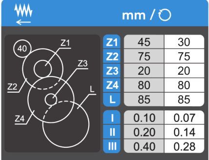
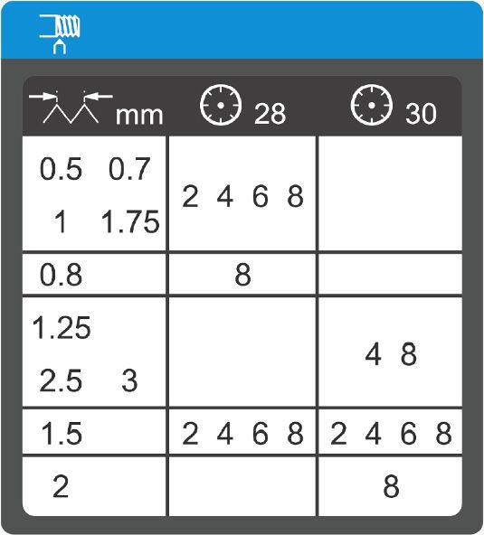
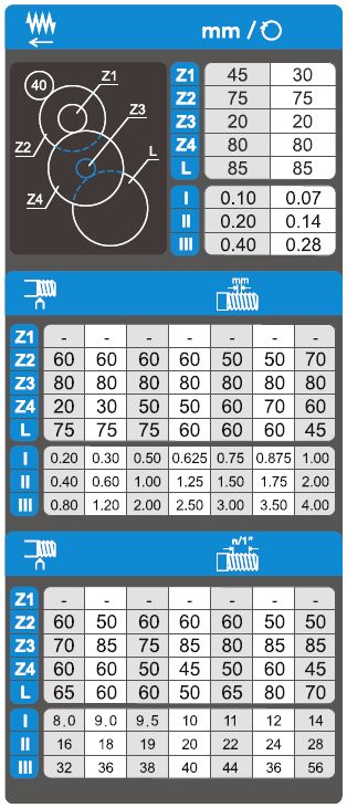
Figure 10‐7: Available feed rates
For example:
Operation feed/rev feed select knob
Stock removal 0,28mm .............................. III
Finishing cut 0.14mm ............................... II
Micro finishing cut 0.07mm ................................ I
NOTE: Three additional feed rates are available with different
change gear setup (Fig 10‐7).
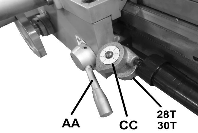
Figure 10‐8: Threading Dial

Figure 10‐9: Threading dial setup
Note:
For thread pitches of 0,2/0,3/0,5/0,6/0,75/ 1,0/ 1,5/3 mm the
half nut can be engaged at any point.
(lead screw pitch = 3 mm = can be divided by thread pitch).
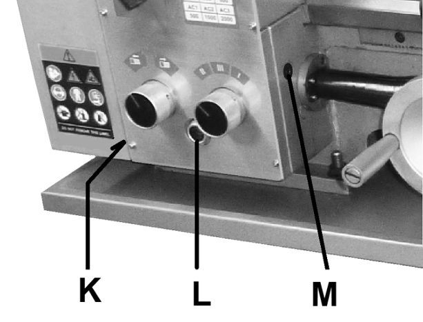
Figure 11‐1: Gearbox oil fill‐up
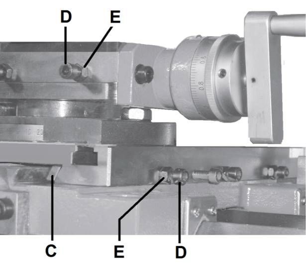
Figure 11‐3: Slide adjustment

Figure 11‐4: Cross slide spindle adjustment
Optionales Zubehör / optional accessories:
PDF-Dokument [1.9 MB]
Bedienungsanleitung / Manual:
Ersatzteilliste / Part List:
PDF-Dokument [6.1 MB]
PDF-Dokument [4.5 MB]
Sollten Sie weitere Fragen haben, zögern Sie nicht uns zu kontaktieren.
Should you have any further questions, please do not hesitate to contact us.


Soziale
Verantwortung
Social Responsibility
Kindertagesstätte Kunterbunt D-90599 Dietenhofen


© ToolParts-Service – Christian Satter / Machinery Group. Alle Rechte vorbehalten. Ersatzteile, Maschinen und Zubehör für Holz- und Metallbearbeitungsmaschinen – JET, PROMAC, © Copyright – ToolParts-Service & Hersteller Alle Inhalte dieser Website, einschließlich Bilder, Texte, technischer Daten, PDF-Dokumente und Ersatzteildokumentationen, unterliegen dem Urheberrecht von ToolParts-Service und/oder den jeweiligen Maschinenherstellern. Jegliche kommerzielle gewerbliche Nutzung ohne vorherige schriftliche Genehmigung ist untersagt und wird konsequent rechtlich verfolgt. © Copyright – ToolParts-Service & Manufacturer All contents of this website, including images, texts, technical data, PDF documents, and spare parts documentation, are subject to the copyright of ToolParts-Service and/or the respective machine manufacturers. Any commercial use without prior written permission is prohibited and will be prosecuted to the full extent of the law.